Section 3: Flight Instruments & Cockpit Displays
Private Pilot Ground School — Updated for 2026
Whether you're learning to fly behind traditional round gauges, a modern glass cockpit, or a combination of both, flight instruments provide critical information about what your airplane is doing.
But learning to fly isn't simply learning how to read instruments.
A safe pilot must understand:
What information an instrument provides
Where that information comes from
What system powers or supplies it
What errors or limitations affect it
How to recognize unreliable information
What to do when an instrument or system fails
And during VFR flight, there is another essential principle:
Keep Your Eyes Outside
Cockpit instruments support situational awareness. They do not replace visual scanning, aircraft control, traffic avoidance, or sound pilot judgment.
This section is based primarily on Chapter 8: Flight Instruments of the FAA's current Pilot's Handbook of Aeronautical Knowledge, FAA-H-8083-25C, together with the FAA-listed October 2025 addendum and the current Private Pilot Airplane ACS, FAA-S-ACS-6C. (Federal Aviation Administration)
What You'll Learn
By the end of this section, you should understand:
-
The traditional six primary flight instruments
-
Pitot-static instruments
-
Traditional gyroscopic instruments
-
Modern electronic flight instruments
-
Airspeed indications and markings
-
Altimeter operation and settings
-
Types of altitude
-
Density altitude
-
Vertical speed indications
-
Attitude and heading information
-
Turn coordination
-
Magnetic compass operation and errors
-
Primary Flight Displays — PFDs
-
Multi-Function Displays — MFDs
-
Air Data Computers — ADCs
-
Attitude and Heading Reference Systems — AHRS
-
Engine-monitoring displays
-
GPS and moving-map information
-
Backup and standby instrumentation
-
Instrument and sensor failures
-
Instrument cross-check
-
Basic instrument maneuvers
-
Automation and mode awareness
-
Electronic weather-display limitations
Most importantly:
You'll learn how to recognize when the information in front of you may be wrong.
1. Your Instruments Tell a Story
No single flight instrument tells you everything about the airplane.
Instead, instruments work together to provide information about:
Attitude • Airspeed • Altitude • Direction • Performance • Position • Engine Operation
Suppose you're trying to maintain straight-and-level flight.
Your attitude indication appears level.
But:
-
Your altimeter shows decreasing altitude
-
Your VSI shows a descent
-
The outside horizon suggests the nose is slightly low
Taken together, those indications tell you the airplane probably isn't maintaining altitude.
Pilots learn to compare multiple sources rather than fixating on one indication.
This is an important part of the:
INSTRUMENT CROSS-CHECK
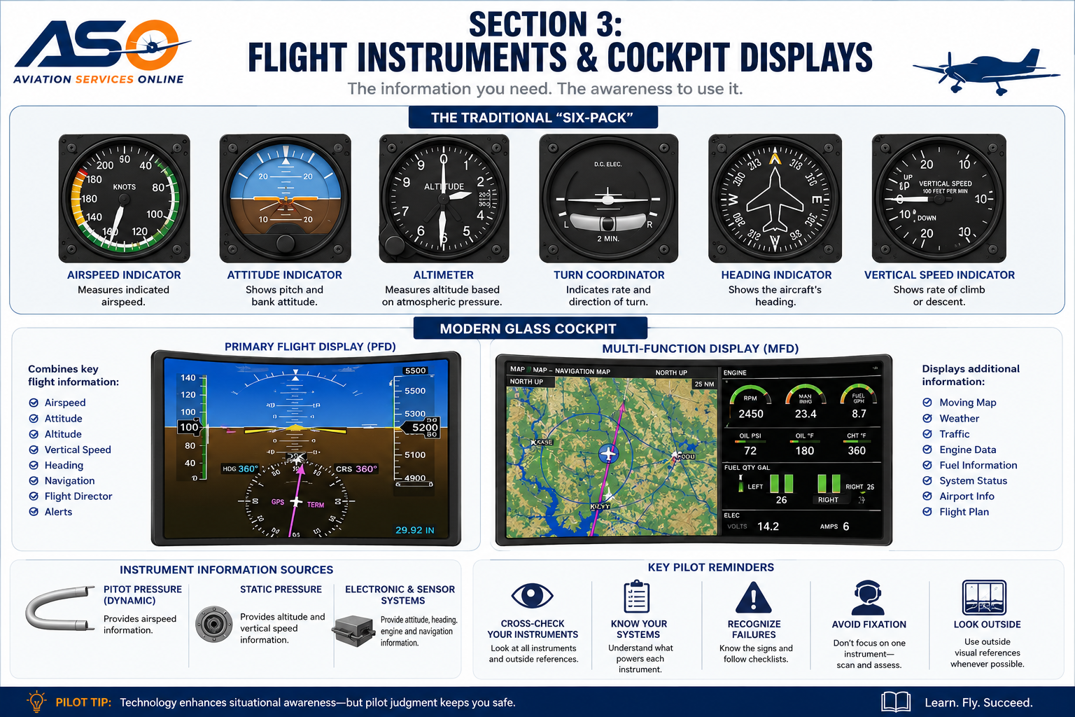
2. The Traditional “Six-Pack”
Many general aviation airplanes use six traditional primary flight instruments commonly arranged in what pilots call the:
SIX-PACK
| Instrument | Information |
|---|---|
| Airspeed Indicator | Airspeed |
| Attitude Indicator | Pitch and bank |
| Altimeter | Altitude |
| Turn Coordinator | Turn and coordination information |
| Heading Indicator | Heading |
| Vertical Speed Indicator | Rate of climb/descent |
However, these instruments don't necessarily receive information or power from the same source.
Traditional aircraft may use combinations of:
-
Pitot pressure
-
Static pressure
-
Vacuum or pressure systems
-
Electrical power
-
Mechanical gyroscopes
Modern airplanes may use electronic sensors and computers instead.
That difference matters when troubleshooting failures.
3. The Pitot-Static System
Three traditional flight instruments rely on the pitot-static system:
AIRSPEED INDICATOR
ALTIMETER
VERTICAL SPEED INDICATOR
The system uses atmospheric pressure in different ways.
Pitot Pressure
A forward-facing pitot opening senses impact, or ram-air, pressure created as the airplane moves through the atmosphere.
Static Pressure
One or more static ports sense atmospheric pressure surrounding the aircraft.
The airspeed indicator uses information from both pitot and static pressure.
The traditional altimeter and VSI use static pressure.
This becomes extremely important when diagnosing instrument problems.
4. Airspeed Indicator
The traditional:
AIRSPEED INDICATOR — ASI
uses the difference between pitot pressure and static pressure to indicate airspeed.
Airspeed in U.S. aviation is commonly displayed in:
KNOTS
One knot equals one nautical mile per hour.
5. Understanding Different Airspeeds
There isn't just one type of airspeed.
Indicated Airspeed — IAS
The speed shown directly on the airspeed indicator, uncorrected for certain instrument and position errors.
Calibrated Airspeed — CAS
Indicated airspeed corrected for instrument and position errors.
True Airspeed — TAS
Calibrated airspeed corrected for altitude and nonstandard temperature.
As altitude increases, true airspeed generally becomes increasingly different from indicated airspeed.
Groundspeed — GS
The aircraft's actual speed across the ground.
Wind affects groundspeed.
For a simplified example:
100 knots TAS + 20-knot tailwind ≈ 120 knots groundspeed
while:
100 knots TAS + 20-knot headwind ≈ 80 knots groundspeed
Groundspeed becomes especially important during cross-country planning.
6. Airspeed Indicator Color Markings
Traditional airspeed indicators use standardized colored markings.
White Arc
Generally represents the:
FLAP OPERATING RANGE
Its upper limit is:
VFE — Maximum Flap-Extended Speed
Green Arc
Generally represents the:
NORMAL OPERATING RANGE
Its upper limit is:
VNO — Maximum Structural Cruising Speed
Yellow Arc
Represents the:
CAUTION RANGE
Operations within this range should generally be conducted only in smooth air and with caution.
Red Line
Represents:
VNE — NEVER-EXCEED SPEED
This speed must not be intentionally exceeded.
The FAA's current Flight Instruments chapter continues to cover these airspeed indications and their operating significance. (Federal Aviation Administration)
7. Important V-Speeds
Private Pilots encounter numerous V-speeds.
Some important examples include:
VS0 — Stall speed or minimum steady flight speed in the landing configuration under specified conditions
VS1 — Stall speed or minimum steady flight speed in a specified configuration
VFE — Maximum flap-extended speed
VNO — Maximum structural cruising speed
VNE — Never-exceed speed
VX — Best angle-of-climb speed
VY — Best rate-of-climb speed
But remember:
V-SPEEDS ARE AIRCRAFT-SPECIFIC.
Never memorize the V-speeds from one training aircraft and assume they apply to another.
Additionally, certain performance speeds may vary based on factors such as:
-
Aircraft weight
-
Configuration
-
Altitude
-
Atmospheric conditions
Always use the appropriate:
POH / AFM
for the airplane you're flying.
8. Altimeter
The altimeter uses static atmospheric pressure to provide altitude information.
Atmospheric pressure normally decreases as altitude increases.
The traditional altimeter translates pressure changes into an altitude indication.
A traditional sensitive altimeter contains an adjustable barometric-pressure setting displayed in the:
KOLLSMAN WINDOW
Pilots set the applicable altimeter setting before and during flight.
9. Pressure Changes and Altimeter Error
An incorrect altimeter setting creates an incorrect altitude indication.
A useful memory aid is:
HIGH TO LOW — LOOK OUT BELOW
If you fly from an area of higher atmospheric pressure toward lower pressure without updating your altimeter setting, your actual altitude can become lower than the altitude indicated.
Temperature also affects the relationship between indicated and true altitude.
The memory aid is useful—but pilots must understand the underlying atmospheric principles rather than relying solely on the phrase.
10. Types of Altitude
Pilots use several definitions of altitude.
Indicated Altitude
Altitude displayed when the altimeter is set to the applicable current altimeter setting.
Pressure Altitude
Altitude indicated when the altimeter is set to:
29.92 inches Hg
Pressure altitude is important in aircraft performance calculations and other aviation applications.
Density Altitude
Pressure altitude corrected for nonstandard temperature.
True Altitude
The aircraft's actual height above mean sea level.
Absolute Altitude
The aircraft's actual height above the terrain directly below it.
11. Density Altitude
Density altitude is one of the most important aircraft-performance concepts a Private Pilot learns.
Higher density altitude means the airplane performs as though it were operating at a higher altitude.
Conditions contributing to higher density altitude include:
-
Higher elevation
-
Higher temperature
-
Lower atmospheric pressure
High density altitude can result in:
-
Longer takeoff rolls
-
Reduced engine performance
-
Reduced propeller performance
-
Reduced climb performance
A runway physically located at 5,000 feet MSL can have a density altitude thousands of feet higher on a hot day.
We'll explore density altitude extensively in the aircraft-performance section.
12. Vertical Speed Indicator
The:
VERTICAL SPEED INDICATOR — VSI
shows the airplane's rate of climb or descent.
Traditional VSIs are normally calibrated in:
FEET PER MINUTE — FPM
For example:
+500 FPM = climbing approximately 500 feet per minute
–500 FPM = descending approximately 500 feet per minute
A traditional VSI operates using static pressure and a calibrated leak.
Because of that design, traditional VSI indications can lag behind the aircraft's actual vertical movement.
13. Traditional Gyroscopic & Modern Electronic Flight Instruments
Traditional airplanes may use mechanically gyroscopic instruments.
Depending on aircraft design, these may be powered by:
-
Vacuum systems
-
Pressure systems
-
Electrical systems
Modern glass-cockpit airplanes can accomplish similar functions using electronic sensors and computers.
Therefore, don't assume:
“Attitude indicator = vacuum powered.”
That might be true in one airplane and completely wrong in another.
Know your aircraft's system architecture.
14. Attitude Indicator
The attitude indicator provides a representation of the airplane's relationship to the horizon.
It primarily displays:
PITCH
and
BANK
Traditional displays normally depict:
Blue = Sky
Brown or dark area = Ground
Electronic attitude displays provide similar information but may derive it from entirely different sensors.
15. Heading Indicator
A traditional heading indicator—often called a directional gyro—provides a relatively stable directional reference.
Unlike the magnetic compass, a traditional heading indicator isn't inherently aligned with Earth's magnetic field.
It can drift.
Therefore, traditional heading indicators must periodically be compared with and realigned to the magnetic compass as appropriate.
Modern electronic heading systems may obtain information from integrated AHRS and magnetometer systems and operate differently.
16. Turn Coordinator
A traditional turn coordinator helps provide information about:
-
Direction of turn
-
Approximate rate of turn
-
Coordination
The inclinometer—the familiar ball—helps the pilot evaluate coordination.
A common training phrase is:
STEP ON THE BALL
If the ball is displaced to the right, appropriate right-rudder pressure generally helps return it toward center.
If displaced left, appropriate left rudder generally helps.
The objective is:
COORDINATED FLIGHT
17. Slip vs. Skid
Uncoordinated flight can produce either a slip or skid.
Slip
Generally occurs when the airplane has too much bank or insufficient rudder relative to the desired turn.
Skid
Generally occurs when excessive rudder is applied in the direction of the turn relative to bank.
This distinction becomes particularly important in the traffic pattern.
Never try to “rudder” the airplane around an overshot final approach.
An excessive inside-rudder input during a base-to-final turn can produce a skidding condition.
If the airplane then stalls, the uncoordinated condition can contribute to spin entry.
At traffic-pattern altitude, recovery may not be possible before ground contact.
If you overshoot final, go around when necessary.
18. Magnetic Compass
The magnetic compass provides directional information by responding to Earth's magnetic field.
It is mechanically simple and independent of many aircraft systems.
But it has important limitations.
Pilots need to understand concepts such as:
-
Magnetic variation
-
Compass deviation
-
Magnetic dip
-
Turning errors
-
Acceleration/deceleration errors
19. Compass Turning Errors — UNOS
In the Northern Hemisphere, a commonly used memory aid for magnetic-compass turning error is:
UNOS
Undershoot North
Overshoot South
This helps pilots remember the behavior of the magnetic compass when rolling out of turns involving northerly and southerly headings.
20. Acceleration Errors — ANDS
Another Northern Hemisphere memory aid is:
ANDS
Accelerate North
Decelerate South
This describes magnetic-compass acceleration/deceleration tendencies most noticeably on easterly and westerly headings.
The acronyms are useful.
Understanding why the compass behaves this way is better.
21. Welcome to the Glass Cockpit
Many modern training aircraft replace several individual mechanical instruments with integrated electronic displays.
A typical glass cockpit may include:
PFD — PRIMARY FLIGHT DISPLAY
and
MFD — MULTI-FUNCTION DISPLAY
But an important rule applies:
Glass-cockpit capabilities vary by aircraft and installation.
Never assume every PFD or MFD provides the same functions.
22. Primary Flight Display — PFD
Depending on the installed equipment, a PFD may display information such as:
-
Airspeed
-
Attitude
-
Altitude
-
Vertical speed
-
Heading
-
Navigation course
-
Flight director information
-
Selected altitude
-
Trend information
-
Alerts
-
GPS information
-
Autopilot modes
The advantage is obvious:
A large amount of flight information can be consolidated onto one display.
But that introduces another challenge:
INFORMATION MANAGEMENT
More information doesn't automatically create better situational awareness.
23. Airspeed Tape
Many electronic flight displays replace the traditional round airspeed indicator with a vertical:
AIRSPEED TAPE
Depending on the installation, it may display:
-
Current airspeed
-
V-speed references
-
Trend information
-
Overspeed indications
-
Low-speed awareness information
-
Selected-speed references
The presentation has changed.
The aerodynamics have not.
24. Altitude Tape
Electronic flight displays may also show altitude on a vertical tape.
Depending on the system, the display may include:
-
Current altitude
-
Selected altitude
-
Altitude trend
-
Barometric setting
-
Altitude alerts
But a digital altimeter is still dependent on valid air-data information.
A sophisticated screen cannot compensate for incorrect pressure information.
25. Horizontal Situation Indicator — HSI
Many electronic flight decks incorporate a:
HORIZONTAL SITUATION INDICATOR — HSI
Depending on the installation, it can combine:
-
Aircraft heading
-
Selected heading
-
Navigation course
-
Course deviation
-
GPS navigation
-
VOR navigation
-
Bearing information
One critical question should always be:
WHAT NAVIGATION SOURCE IS SELECTED?
A beautifully displayed course is useless if you've selected the wrong source.
26. Multi-Function Display — MFD
Depending on equipment and installation, an MFD may provide:
-
Moving map
-
Terrain information
-
Traffic information
-
Weather information
-
Airport information
-
Flight plans
-
Engine information
-
Fuel information
-
Navigation information
-
Aircraft-system status
An MFD can significantly increase situational awareness.
But:
THE MAP IS NOT THE TERRITORY.
A moving map doesn't eliminate the need to:
-
Look outside
-
Understand airspace
-
Monitor weather
-
Maintain aircraft control
-
Manage fuel
-
Verify position
-
Exercise judgment
27. Electronic Engine Displays
Modern aircraft may replace traditional engine gauges with electronic displays.
Depending on installation, these may show:
-
RPM
-
Oil pressure
-
Oil temperature
-
Fuel quantity
-
Fuel flow
-
Electrical voltage
-
Electrical current
-
Exhaust gas temperature — EGT
-
Cylinder head temperature — CHT
-
Engine warnings and alerts
The pilot still needs to know:
What is normal?
What is abnormal?
What requires action?
Use the aircraft POH/AFM and checklist.
28. AHRS — Attitude and Heading Reference System
Many modern electronic flight displays use an:
AHRS
The Attitude and Heading Reference System provides electronic attitude and heading information to applicable cockpit systems.
It replaces functions historically performed by certain mechanical gyroscopic instruments.
29. ADC — Air Data Computer
An:
AIR DATA COMPUTER — ADC
processes information from air-data sources.
Depending on the installation, it can provide information used to display:
-
Airspeed
-
Altitude
-
Vertical speed
-
Temperature-related information
This leads to an important lesson:
One sensor or computer failure can affect several displayed indications.
30. Redundancy and Backup Instruments
Electronic displays can fail.
Possible causes include:
-
Electrical failure
-
Display failure
-
Sensor failure
-
Data-source failure
-
Software malfunction
-
AHRS failure
-
ADC failure
-
Pitot-static problems
Aircraft may therefore incorporate:
-
Standby instruments
-
Independent attitude sources
-
Standby batteries
-
Multiple displays
-
Redundant electrical systems
Don't simply ask:
“Where is the backup?”
Ask:
WHAT POWERS IT?
IS ITS DATA SOURCE INDEPENDENT?
HOW LONG WILL IT OPERATE?
WHAT INFORMATION WILL I LOSE?
31. Recognizing Instrument Failures
Imagine your electronic display suddenly shows questionable:
-
Airspeed
-
Altitude
-
Vertical speed
while attitude and heading appear normal.
What do those three questionable indications have in common?
Air-data information.
Now imagine attitude and heading information become unreliable while airspeed and altitude appear reasonable.
That suggests a different system or sensor problem.
Don't simply think:
“The screen is broken.”
Instead ask:
WHICH SOURCE PROVIDES THIS INFORMATION?
WHAT OTHER INDICATIONS SHOULD BE AFFECTED?
WHAT INFORMATION CAN I STILL TRUST?
That's how pilots diagnose instrument problems.
32. Pitot-System Blockage
A pitot-system blockage can produce erroneous airspeed indications.
But don't memorize:
“Blocked pitot tube = zero airspeed.”
That's not always true.
The resulting indication depends upon:
-
Which opening is blocked
-
Whether the drain hole is blocked
-
Whether pressure becomes trapped
-
Whether static pressure remains available
Understand the system instead of memorizing one failure indication.
33. Static-System Blockage
A blocked static source can affect several traditional instruments.
These may include:
ALTIMETER
VSI
AIRSPEED INDICATOR
A traditional altimeter may remain near the altitude where the blockage occurred.
A traditional VSI generally trends toward zero.
The airspeed indicator can provide erroneous indications because it depends on both pitot and static pressure.
Some aircraft provide an:
ALTERNATE STATIC SOURCE
Using alternate static air may restore usable information, although indications may differ somewhat from normal.
Consult the POH/AFM.
34. Basic Instrument Maneuvers
Private Pilot training includes basic instrument skills.
The current Private Pilot Airplane ACS formally identifies these as:
BASIC INSTRUMENT MANEUVERS
The current ACS includes tasks involving:
-
Straight-and-level flight
-
Constant-airspeed climbs
-
Constant-airspeed descents
-
Turns to headings
-
Recovery from unusual flight attitudes
-
Radio communications, navigation systems/facilities, and radar services appropriate to the operation
This is more precise than simply describing Private Pilot training as “partial-panel flying.”
FAA-S-ACS-6C remains the current Private Pilot Airplane ACS in 2026. (Federal Aviation Administration)
35. Why Does a VFR Pilot Need Instrument Training?
A Private Pilot Certificate doesn't authorize a non-instrument-rated pilot to intentionally operate in instrument meteorological conditions.
So why learn basic instrument flying?
Because VFR pilots can unexpectedly encounter:
-
Clouds
-
Haze
-
Smoke
-
Darkness
-
Reduced visibility
-
Loss of a discernible horizon
If outside visual references are unexpectedly lost, basic instrument skills can help the pilot maintain aircraft control while taking appropriate action.
Basic instrument training is a safety skill—not authorization to intentionally fly IFR.
36. Instrument Cross-Check
A good pilot continually compares information.
During cruise, an illustrative cross-check might include:
Outside horizon → attitude → altitude → airspeed → heading → engine indications → outside traffic
There isn't one universal scan sequence for every aircraft and situation.
The important principle is:
DON'T FIXATE.
A pilot staring at one instrument can miss a developing problem elsewhere.
37. Automation Is a Tool
Modern aircraft may contain:
-
GPS
-
Autopilots
-
Flight directors
-
Electronic checklists
-
Traffic displays
-
Terrain displays
-
Electronic weather information
These systems can reduce pilot workload.
They can also create new risks.
A pilot can become so focused on programming avionics that aircraft control and traffic scanning suffer.
This is sometimes called excessive:
HEADS-DOWN TIME
If programming the avionics interferes with flying the airplane:
FLY FIRST.
38. Automation Mode Awareness
Autopilots and flight directors operate according to selected modes.
Pilots should continually know:
What mode is active?
What mode is armed?
What will the airplane do next?
This is:
MODE AWARENESS
An autopilot that appears to be doing something “wrong” may actually be doing exactly what was selected.
If you're uncertain about what the automation is doing, maintain aircraft control and, when appropriate, disconnect the automation and fly manually in accordance with the aircraft procedures.
39. Electronic Weather Displays
Modern avionics can display extremely useful weather information.
But there is an essential limitation:
DATALINK WEATHER IS NOT NECESSARILY REAL-TIME WEATHER.
Information must be:
Collected → Processed → Transmitted → Received → Displayed
That process takes time.
The FAA's active AC 00-63B, Use of Flight Deck Displays of Digital Weather and Aeronautical Information, specifically addresses best practices and limitations associated with flight-information data links. (Federal Aviation Administration)
Therefore:
DO NOT USE DATALINK WEATHER FOR TACTICAL THUNDERSTORM PENETRATION OR CLOSE-IN THUNDERSTORM AVOIDANCE.
A displayed precipitation image can represent where hazardous weather was, rather than exactly where it is now.
Pilots need to understand:
-
Data age
-
Product age
-
Update intervals
-
Latency
-
Display limitations
-
Coverage limitations
We'll examine these concepts in detail during weather training.
40. Keep Your Eyes Outside
One of the easiest mistakes to make in a sophisticated cockpit is spending too much time staring at the screens.
During VFR flight:
LOOK OUTSIDE.
You still need to visually monitor:
-
Other aircraft
-
Terrain
-
Clouds
-
Runways
-
Obstacles
-
Birds
-
Traffic patterns
-
Aircraft attitude
Glass-cockpit technology can enhance situational awareness.
It doesn't eliminate your visual responsibilities.
41. Scenario: Your Airspeed Doesn't Look Right
You're climbing after takeoff.
The airplane's:
-
Pitch attitude looks normal
-
Engine sounds normal
-
Power appears normal
But the airspeed indication looks unusually low.
Should you immediately push the nose down?
NOT NECESSARILY.
First maintain aircraft control and cross-check:
-
Outside attitude
-
Power
-
Other flight instruments
-
Known aircraft performance
-
Pitot-static indications
-
Applicable checklist
Don't let one potentially erroneous indication cause an inappropriate control input.
42. Scenario: Your Glass Cockpit Goes Dark
You're flying during daylight in good VFR conditions.
The primary electronic display suddenly goes dark.
What's your first priority?
FLY THE AIRPLANE.
Use:
-
Outside visual references
-
Remaining displays
-
Standby instruments
-
Backup systems
Then:
-
Diagnose the problem
-
Follow the checklist
-
Manage electrical load when applicable
-
Determine whether continuing the flight is prudent
A display failure is a problem.
Losing aircraft control while staring at the failed display is a much bigger problem.
43. Scenario: GPS Says You're Perfectly on Course
Your moving map shows the airplane centered perfectly on the magenta line.
Does that guarantee your flight is safe?
NO.
You could still be:
-
Flying toward hazardous weather
-
Approaching terrain
-
Entering inappropriate airspace
-
Low on fuel
-
Following an incorrectly programmed route
-
Using the wrong navigation source
-
Heading toward the wrong airport
Technology provides information.
THE PILOT PROVIDES JUDGMENT.
44. Scenario: Your Instruments Disagree
Your attitude display appears to show a bank.
But:
-
The outside horizon appears level
-
Heading isn't changing as expected
-
Independent turn information doesn't support the displayed bank
What failed?
Don't diagnose too quickly.
One possibility is an unreliable attitude indication.
But the correct response begins by:
CROSS-CHECKING INDEPENDENT INFORMATION.
Ask:
-
Which indications agree?
-
Which indications disagree?
-
Which systems supply those indications?
-
Which sources are independent?
-
Is the outside visual reference reliable?
Cross-check first. Diagnose second.
45. Think Like the ACS
For every instrument or cockpit system, ask three questions.
KNOWLEDGE
What does it tell me and where does the information come from?
RISK MANAGEMENT
What could happen if I misunderstand or lose that information?
SKILL
Can I recognize abnormal indications and continue controlling the airplane safely?
The current Private Pilot ACS specifically integrates knowledge, risk management, and skill throughout the evaluation process. (Federal Aviation Administration)
Section 3 Review
By the end of this section, you should understand:
-
Traditional six-pack instruments
-
Pitot and static pressure
-
Pitot-static instruments
-
IAS, CAS, TAS, and groundspeed
-
Airspeed indicator markings
-
Common V-speeds
-
Altimeter operation
-
Altimeter settings
-
Pressure altitude
-
Density altitude
-
VSI operation
-
Traditional gyroscopic instruments
-
Modern electronic flight instruments
-
Attitude and heading information
-
Turn coordination
-
Slips and skids
-
Magnetic compass limitations
-
UNOS and ANDS in the Northern Hemisphere
-
PFD and MFD functions
-
AHRS
-
ADC
-
Backup instrumentation
-
Pitot-static failures
-
Instrument cross-check
-
Basic instrument maneuvers
-
Automation and mode awareness
-
Datalink weather limitations
-
The importance of maintaining an outside visual scan during VFR flight
2026 Knowledge Check
1. Which three traditional flight instruments use the pitot-static system?
Airspeed indicator, altimeter, and vertical speed indicator.
2. Which traditional instrument uses both pitot and static pressure?
The airspeed indicator.
3. What does VNE mean?
Never-exceed speed.
4. What does the white arc generally represent?
The flap operating range.
5. What is pressure altitude?
The altitude indicated when the altimeter is set to:
29.92 inches Hg.
6. What is density altitude?
Pressure altitude corrected for nonstandard temperature.
7. What information does a traditional turn coordinator provide?
It provides information about the direction and approximate rate of turn, along with an inclinometer used to evaluate coordination.
8. What does PFD stand for?
Primary Flight Display.
9. What does MFD stand for?
Multi-Function Display.
10. What does AHRS provide in applicable electronic flight-display systems?
Attitude and heading reference information.
11. What does an ADC provide in applicable electronic systems?
It processes air-data information used for indications such as airspeed, altitude, and vertical speed.
12. Does a blocked pitot tube always cause the airspeed indicator to read zero?
NO.
The resulting indication depends on the exact nature of the blockage.
13. Can one sensor or computer failure affect several indications on a glass cockpit?
Yes.
That's why understanding system architecture is important.
14. Is datalink weather necessarily showing current real-time conditions?
NO.
Latency exists between observation, processing, transmission, reception, and display.
15. Should datalink weather be used for tactical thunderstorm penetration?
NO.
16. Does having a GPS moving map eliminate the need to look outside during VFR flight?
ABSOLUTELY NOT.
17. If instruments disagree, should you immediately assume the most unusual indication is the failed instrument?
No. Cross-check independent information first.
18. What is your first responsibility if a major cockpit display fails?
FLY THE AIRPLANE.
Pilot Decision-Making Exercise
Imagine you're flying a modern glass-cockpit trainer on a beautiful VFR afternoon.
The aircraft has:
-
GPS
-
Moving map
-
Traffic information
-
Datalink weather
-
Terrain information
-
Electronic engine monitoring
-
Autopilot
The airplane appears to know:
Where you are.
Where you're going.
What's around you.
It can even help fly the route.
It's tempting to think:
“The airplane basically flies itself.”
That's exactly the mindset a pilot must avoid.
Ask yourself:
What if the GPS fails?
What if the PFD fails?
What if the ADC fails?
What if the AHRS fails?
What if the autopilot disconnects?
What if the displayed weather is older than I realize?
What if traffic isn't displayed?
What if I selected the wrong navigation source?
What if I entered the wrong airport?
And finally:
CAN I STILL FLY THE AIRPLANE?
Technology should make a capable pilot:
MORE INFORMED.
It should never make the pilot:
LESS CAPABLE.
Key Takeaway
Whether you're looking at six traditional round instruments or an advanced integrated glass cockpit, your responsibilities remain fundamentally the same.
A safe pilot understands:
WHAT THE INSTRUMENT IS TELLING YOU
WHERE THE INFORMATION COMES FROM
WHAT SYSTEM PROVIDES IT
WHETHER YOU CAN TRUST IT
WHAT OTHER INFORMATION CONFIRMS IT
WHAT HAPPENS IF IT FAILS
and above all: